Chapter 3 — Understanding the RCR Windkessel Model
Windkessel models provide a compact way to represent the hemodynamic influence of the circulation that lies beyond a modeled vascular domain. Among these models, the three-element RCR formulation is widely used because it combines vascular resistance, arterial compliance, and proximal impedance within a simple lumped-parameter framework. Understanding how these elements interact is essential before RCR models can be meaningfully assigned to vascular outlets or coupled to higher-dimensional simulations [1,2].
As discussed in Chapter 1, a truncated vascular domain requires a representation of the circulation that continues beyond its outlets. Rather than explicitly reconstructing the entire downstream vascular tree, the Windkessel approach represents its dominant hemodynamic effects using a small number of lumped elements. The three-element RCR model is one of the most widely used formulations for this purpose.
What do , , and represent?
The three-element Windkessel model represents the downstream circulation using two resistive elements and one compliant element. Although the model is often drawn as a simple electrical analogue, each component has a specific hemodynamic interpretation.
The first element, proximal resistance (), is placed directly downstream of the vascular outlet. It represents the immediate opposition encountered by pulsatile flow as it enters the unresolved arterial system and is commonly interpreted as a lumped approximation of the characteristic impedance of the proximal downstream vasculature [1]. In practical terms, influences the rapid pressure response to changes in flow and therefore contributes strongly to the relationship between instantaneous pressure and flow during systole.
The second resistive element, distal resistance (), represents the dominant resistance of the more distal vascular bed. Much of the resistance to systemic blood flow arises in smaller arteries and arterioles, where vessel diameters become progressively smaller. In many systemic arterial applications, constitutes the larger fraction of the total resistance and therefore plays a major role in determining the mean pressure required to sustain a given mean flow [1,2].
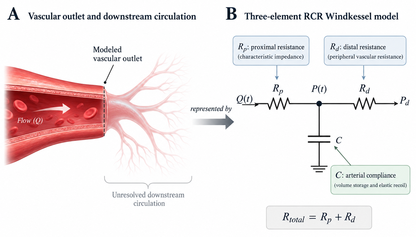
Figure 3.1. Physiological interpretation and circuit representation of the three-element RCR Windkessel model. (A) A computational vascular outlet represents an artificial truncation of the physiological circulation, while the unresolved downstream vascular bed continues to influence pressure and flow within the modeled domain. (B) The downstream circulation is approximated using a proximal resistance (), distal resistance (), and arterial compliance (). represents the proximal or characteristic impedance, represents the dominant peripheral vascular resistance, and represents the ability of the arterial system to temporarily store and release blood volume. The total resistance is given by .
Together, the two resistances define the total resistance assigned to an outlet:
This total resistance largely determines the mean pressure–flow relationship across the downstream circulation. However, resistance alone cannot reproduce the pulsatile behavior of the arterial system.
The third element, compliance (), introduces the ability to temporarily store blood volume. Large and medium-sized arteries expand as pressure rises during systole, allowing part of the ejected blood volume to be stored within the arterial system. During diastole, elastic recoil releases this stored volume and helps maintain forward flow even when ventricular ejection has ceased [1,2].
In the RCR model, this behavior is represented by the compliant element connected between the proximal and distal resistances. A larger compliance allows more volume to be accommodated for a given change in pressure, whereas a smaller compliance produces a larger pressure change for the same volume variation.
The three components therefore describe complementary aspects of the downstream vascular load [1,2]:
- represents the proximal or characteristic impedance experienced by pulsatile flow.
- represents the dominant peripheral resistance of the distal circulation.
- represents the ability of the arterial system to store and release blood volume.
Their arrangement is equally important. In the classical three-element Windkessel configuration, is placed in series with a parallel combination of and . This arrangement allows the model to respond differently to rapid pulsatile changes and to the slower pressure decay associated with arterial storage and peripheral flow.
In other words, the RCR model separates the vascular load into three related effects: the immediate response to incoming pulsatile flow, the resistance imposed by the peripheral circulation, and the elastic storage capacity of the arterial system. The interaction among these effects determines how outlet pressure evolves in response to a time-varying flow waveform.
How does the RCR model relate pressure and flow?
The RCR model converts a time-varying outlet flow rate into a corresponding pressure response. This relationship arises from the interaction between the two resistances and the compliant element rather than from any single parameter alone.
Let the variable represent the flow entering the RCR model, and the variable represent the pressure at the vessel outlet. The pressure immediately downstream of the proximal resistance can be represented by an internal pressure state, . The pressure drop across is then;
This first relation shows the immediate resistive contribution of the proximal element: rapid changes in flow produce an instantaneous pressure change proportional to .
Downstream of , the incoming flow is partitioned between the distal resistance and the compliant element. Conservation of flow at this node gives
where is the distal or reference pressure [1,2].
This equation describes the dynamic part of the RCR model. Part of the incoming flow passes through the distal resistance, while the remainder is temporarily stored by the compliant element. When inflow approaches zero, the compliant pressure decays toward the distal pressure with a characteristic time scale governed by .
where is the Windkessel time constant [1,4].
The time constant provides an intuitive measure of how rapidly pressure decays after the driving flow decreases. A larger produces a slower pressure decay, whereas a smaller produces a more rapid decay. In physiological terms, the combined effects of distal resistance and arterial compliance therefore strongly influence the diastolic portion of the pressure waveform.
More generally, , , and affect different features of the pulsatile pressure response. primarily influences the rapid pressure response associated with pulsatile inflow, strongly affects the downstream resistive load and pressure level, and governs the extent to which pressure variations are buffered by arterial volume storage. These qualitative effects are illustrated in Figure 3.2.

Figure 3.2. Effect of RCR parameters on the outlet pressure waveform. (A) Prescribed pulsatile inflow, . (B–D) Qualitative effects of varying proximal resistance (), distal resistance (), and arterial compliance () while the remaining parameters are held constant. Increasing primarily amplifies the immediate systolic pressure response, increasing elevates the downstream pressure level and slows diastolic decay, and increasing smooths the waveform and reduces the pressure peak.
How are RCR parameters determined?
RCR parameters should reflect the hemodynamic load imposed by the vascular territory represented beyond each computational outlet. There is no single universal parameterization method, because the available physiological information may differ between applications. Nevertheless, most approaches begin with target pressure and flow conditions and use them to estimate resistance and compliance.
For a periodic circulation, the mean flow through the compliant element over one cardiac cycle is zero. The mean pressure–flow relationship is therefore governed primarily by the total resistance,
where and are the target mean outlet pressure and flow rate, and is the distal pressure. This relation provides a convenient first estimate of the total downstream resistance required to reproduce the intended mean hemodynamic state [1,3].
The total resistance must then be divided between and . Ideally, is related to the characteristic impedance of the proximal downstream arterial system, while the remaining resistance is assigned to . When detailed impedance information is unavailable, practical parameterization strategies may estimate this partition from physiological assumptions, literature values, or calibration against measured pressure and flow waveforms [1,3]. Once has been selected,
provides the corresponding distal resistance.
Compliance is determined from the ability of the downstream arterial system to store volume as pressure changes. When a characteristic pressure-decay time is available or prescribed, the Windkessel relation
provides a direct connection between compliance and the diastolic time constant [3,4]. Alternatively, compliance may be estimated from pressure–volume information or adjusted so that the resulting pulsatile pressure waveform reproduces the desired systolic–diastolic behavior.
For vascular models with multiple outlets, this procedure is applied separately to each downstream territory. Target flow fractions can be used to define outlet-specific mean flows and therefore outlet-specific resistances, while compliance can likewise be distributed according to the assumed properties of the corresponding vascular beds [5].
In practice, these calculations usually provide an initial RCR parameter set rather than a guaranteed final solution. The resulting pressure waveform, mean flow distribution, and other physiological targets should be checked after simulation, and the parameters may require refinement when the coupled model does not reproduce the intended hemodynamic behavior [3,5].
As a lumped representation, the RCR model captures the net hemodynamic influence of the unresolved downstream circulation rather than its spatially distributed vascular structure. Once an appropriate RCR parameter set has been defined, the model can be coupled to a vascular outlet so that the downstream pressure responds dynamically to the flow leaving the computational domain. The numerical logic of this interaction and the exchange of information between 0D and 3D models are discussed in Chapter 4.
References
[1] Westerhof N, Lankhaar JW, Westerhof BE. The arterial Windkessel. Medical & Biological Engineering & Computing. 2009;47:131–141. doi:10.1007/s11517-008-0359-2.
[2] Shi Y, Lawford P, Hose R. Review of Zero-D and 1-D Models of Blood Flow in the Cardiovascular System. BioMedical Engineering OnLine. 2011;10:33. doi:10.1186/1475-925X-10-33.
[3] Kind T, Faes TJC, Lankhaar JW, Vonk-Noordegraaf A, Verhaegen M. Estimation of three- and four-element Windkessel parameters using subspace model identification. IEEE Transactions on Biomedical Engineering. 2010;57:1531–1538. doi:10.1109/TBME.2010.2041351.
[4] Stergiopulos N, Meister JJ, Westerhof N. Evaluation of methods for estimation of total arterial compliance. American Journal of Physiology. 1995;268(4 Pt 2):H1540–H1548. doi: 10.1152/ajpheart.1995.268.4.H1540.
[5] Spilker RL, Taylor CA. Tuning multidomain hemodynamic simulations to match physiological measurements. Annals of Biomedical Engineering. 2010;38(8):2635–2648. doi: 10.1007/s10439-010-0011-9.
